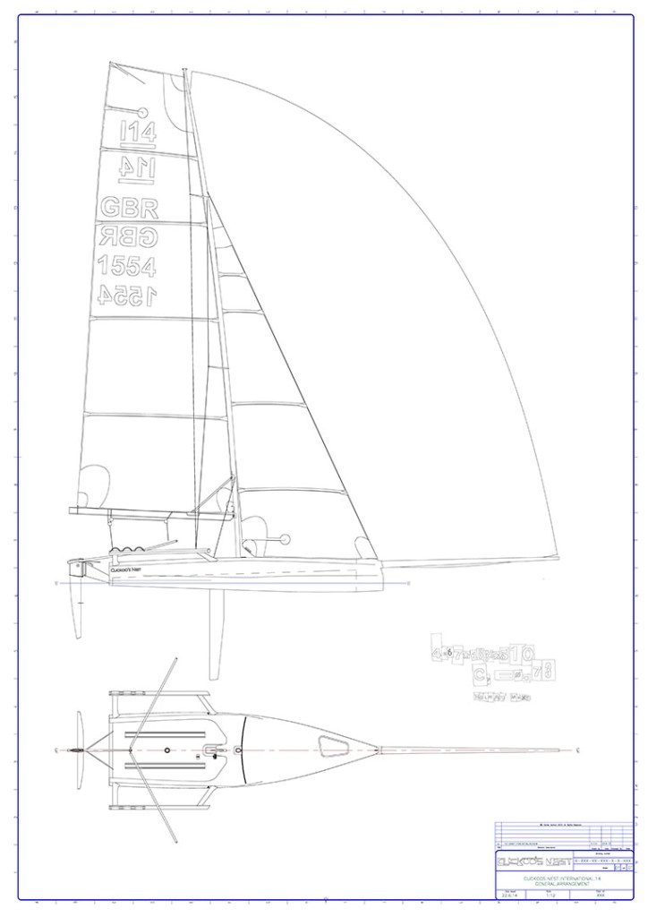
CUCKOO’S NEST – DAN HOLMAN DESIGN
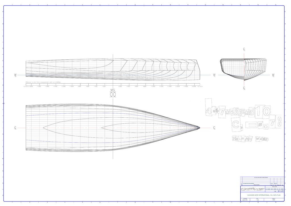
The intent of the cuckoos nest design was to offer drag reduction across the entire speed range at the displacement (net of tfoil lift) and trim combinations seen with modern tfoil use.
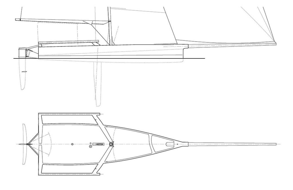
As well as optimising traditional hydrostatic quantities across the speed / displacement / trim combinations, the main differentiator of the cuckoos nest is that the rise of floor chine is locally kinked, so that the intent of the rule is challenged with a minimised waterline beam, whilst keeping a fair hullform. To improve speed in the planing regime, another chine has been placed in the aft third to engage at, but not before typical trim/displacement combinations seen at around 12kts boatspeed and above. The cuckoos nest also features a spray rail forward to split the bow wave, reducing wetting and drag at higher semi displacement speeds ie 8-12 knots.
The design also features aft mast placement, reverse shear and a dreadnought bow to reduce non essential weight and Windage. The fwd and aft wing bars are extensions of the X frame and transom respectively.
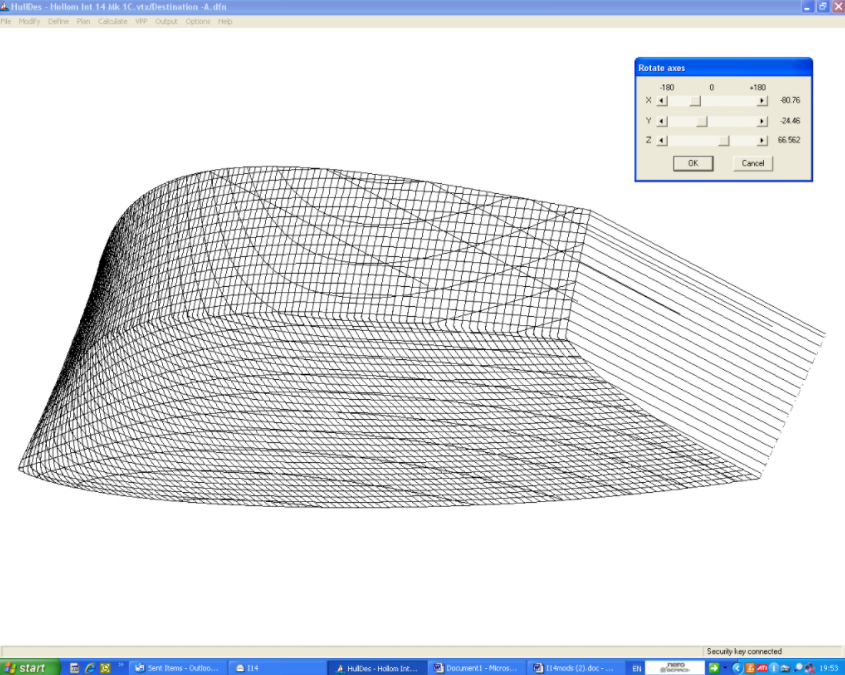
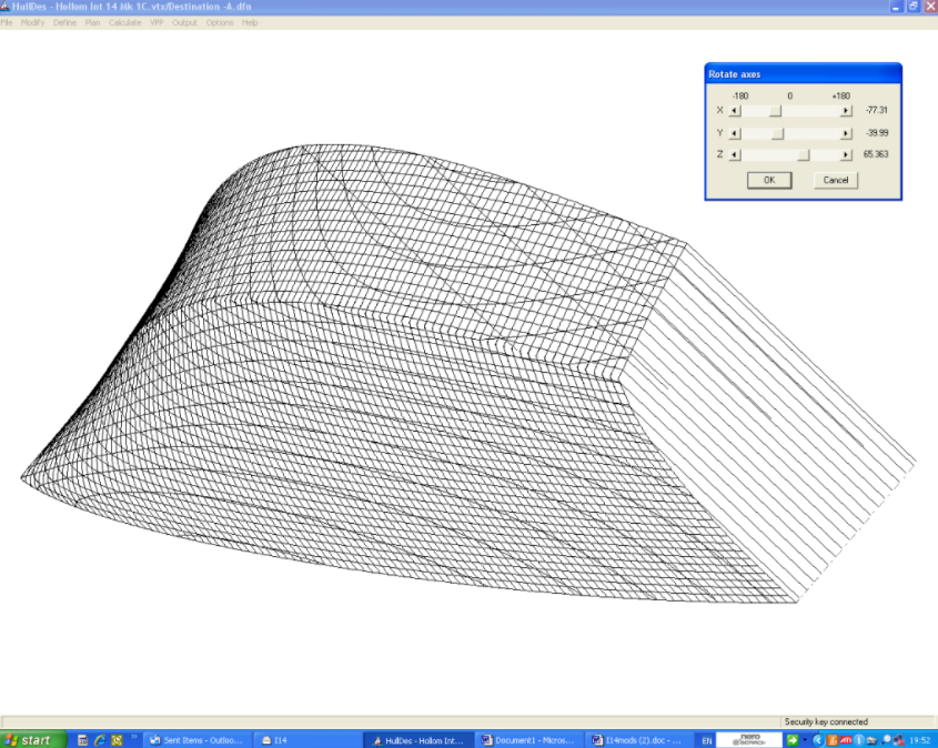
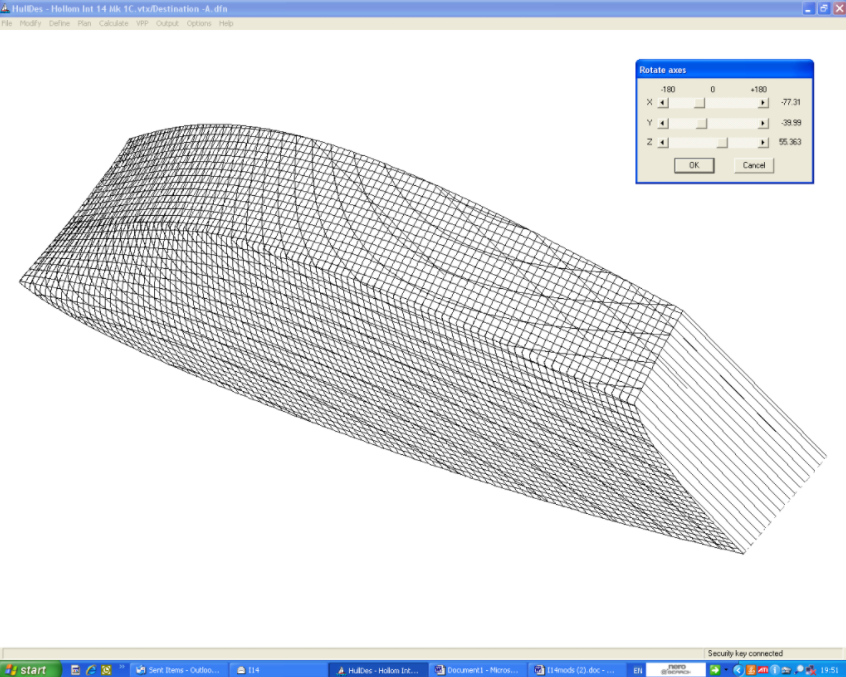
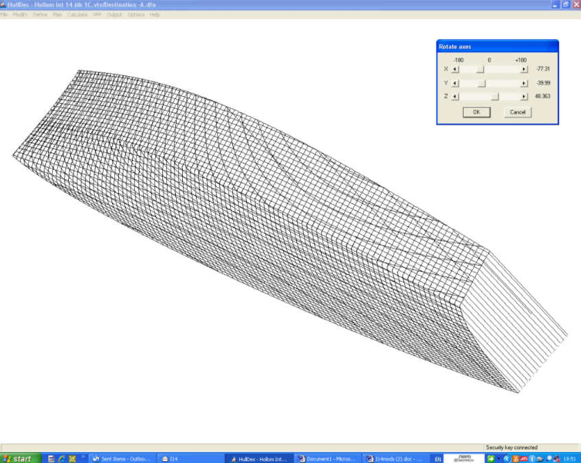
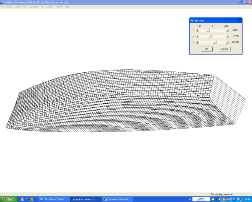
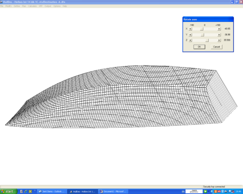
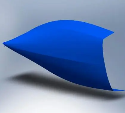
DEPARTURE – DAVID HOLLOM DESIGN
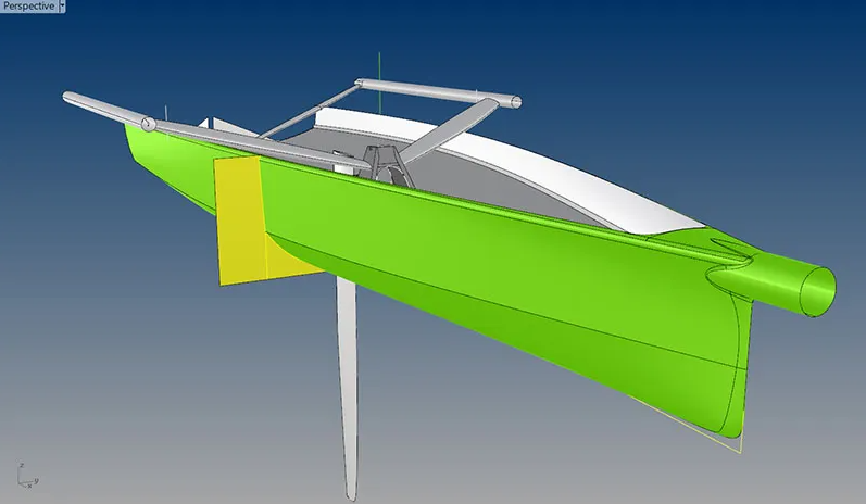
As the name suggests the design is a departure from the traditional dinghy shape.
In a planing dinghy the aim should be to get the boat on the plane sooner, be faster whilst on the plane and to hold the plane longer whilst not compromising displacement speed. Fortunately, reducing drag at displacement speed allows you to sail faster so that you reach planing speed sooner so there is no compromise here.
Wave drag and viscous drag are of course the two major hydrodynamic drags at displacement speed. Viscous drag is present at all speeds but forms the largest proportion of drag at low speeds. The main determinant of viscous drag is wetted surface area. Likewise, wave drag is present at all speeds but this time forms the largest proportion at high speeds. High prismatic coefficients reduce wave drag at high speeds and increase it at low speeds but, as the contribution of wave drag at low speeds is small it is preferable, in a high-speed craft, to have a high prismatic. The hit at low speeds, which are anyway not visited much, is small.
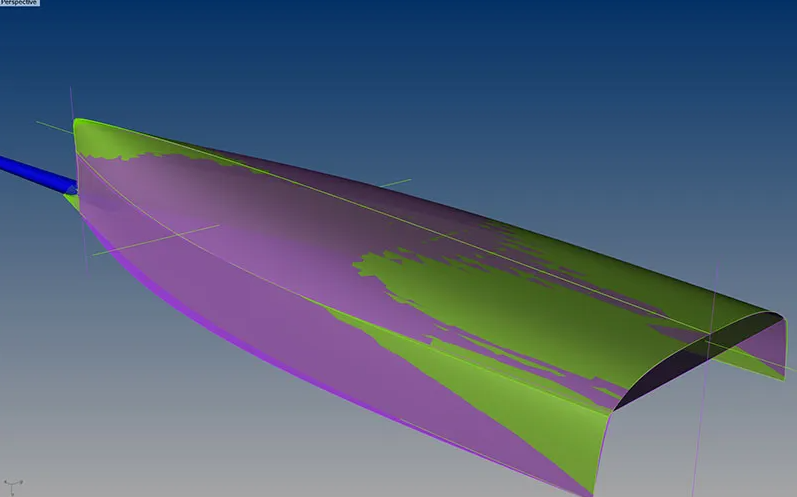
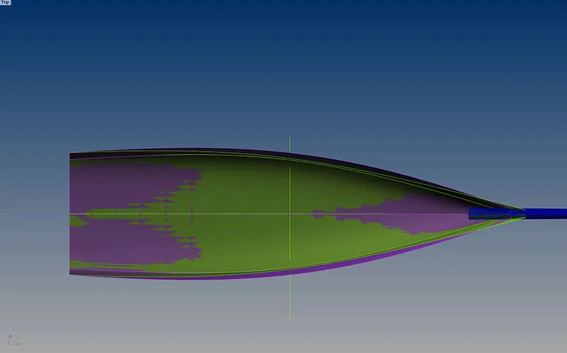
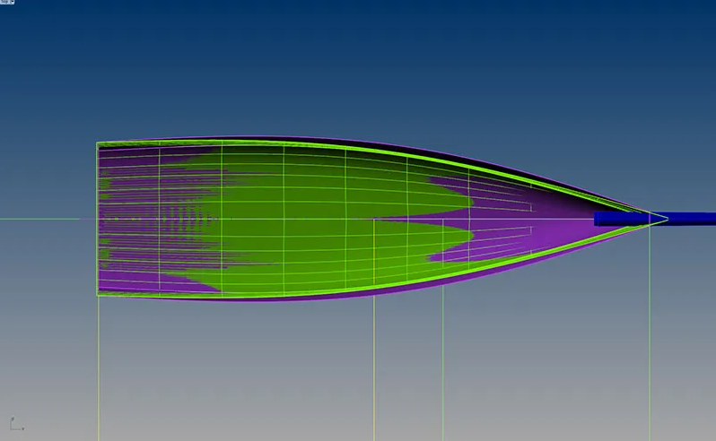
Once on the plane planing speed is determined by the efficiency of the lifting surface, in this case the bottom of the boat. Quite simply V sections are more efficient planing surfaces than U sections. (When did you last see a U sectioned planing powerboat). If you have a better planing shape it will not only plane faster but will remain on the plane longer so the last design aim is also satisfied.
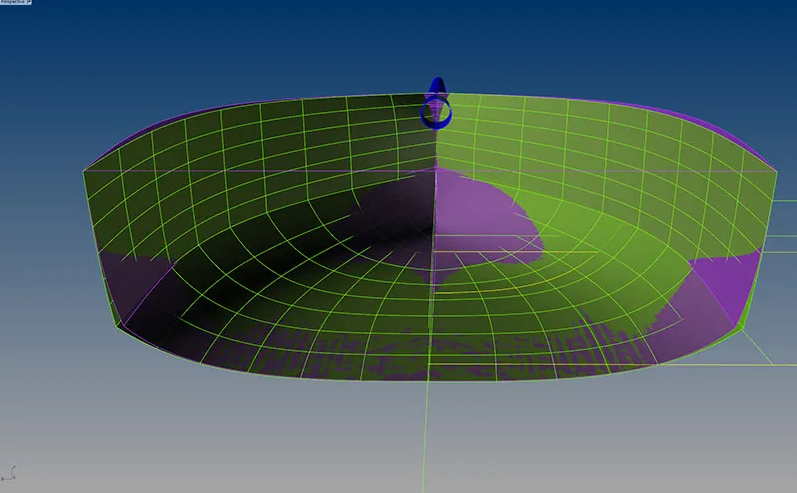
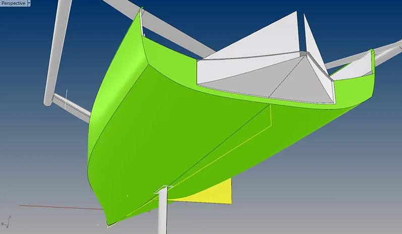
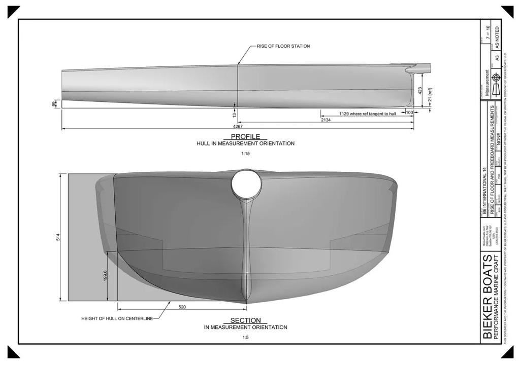
The task was therefore to reduce wetted surface, increase prismatic and, as waterline beam is a big driver of wave drag and also increases wetted area, reduce waterline beam. Sounds easy but unfortunately almost everything you do to reduce wave drag increases wetted area (increasing prismatic always increases wetted area) and almost everything you do to reduce wetted area increases wave drag. About the only thing that reduces both is a reduction in waterline beam. However, by carefully changing the sectional shape along the length from U in the bow to V in the middle and to a flat U at the stern it has been possible to have a narrower waterline beam whilst still complying with the rise of floor rule, a higher prismatic and a lower wetted surface area. The U section bow raises prismatic at displacement speeds when it is in the water but at planing speeds it is clear of the water and the boat planes on its V sections in the middle and the flat stern sections.
As a comparison, the more important hydrostatics of “Departure” (Hollom 1) and the Bieker 5 are as follows:-
| Bieker 5 | Hollom 1 | % Difference | |
|---|---|---|---|
| Waterline beam | 1.00838 | 0.95088 | -5.6% |
| Wetted surface area | 3.33329 | 3.23134 | -3.06% |
| Prismatic Coefficient | 0.63003 | 0.67056 | +6.4% |
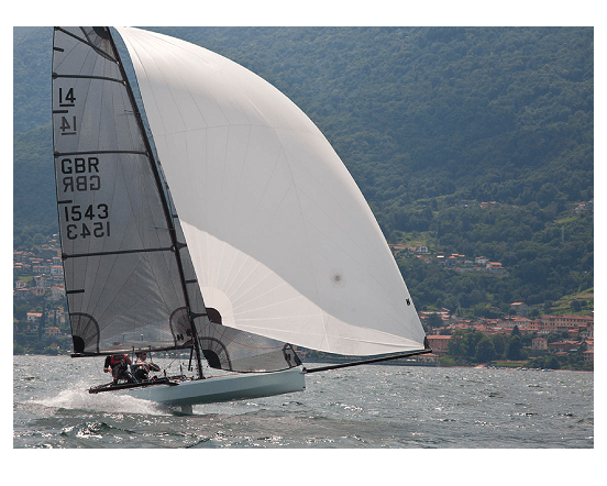
Sailing experience to date confirms that the design aims were achieved with the boat planing sooner, planing faster and remaining on the plane longer.
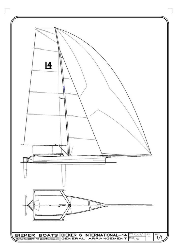
BIEKER 5 & 6 – PAUL BIEKER DESIGN